


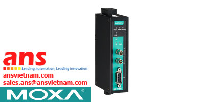
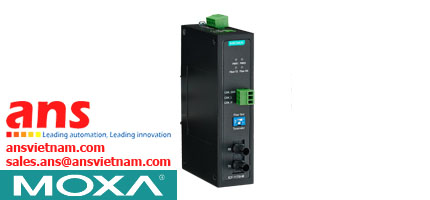
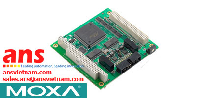
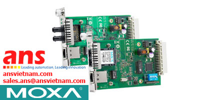
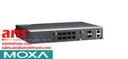
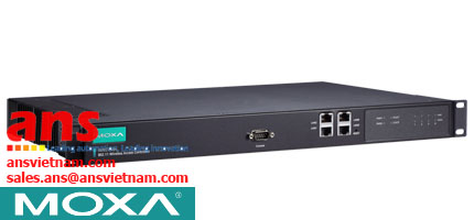
Fieldbus-to-Fiber Converters ICF-1280I Series Moxa vietnam
Xuất sứ: Moxa VietNam
Nhà cung cấp: Moxa VietNam ANS VietNam
Hãng sản xuất: Moxa
Fieldbus-to-Fiber Converters ICF-1280I Series Moxa vietnam
Features and Benefits
- Redundant fiber ring with zero recovery time
- Examine network-wide fiber communication from a single converter
- Auto baudrate detection and data speed up to 12 Mbps
- PROFIBUS Bus Fail prevents corrupted datagram in functioning segment
- Alarm by relay output
- 2 kV galvanic isolation protection
- Dual-power inputs for redundancy
- Extends PROFIBUS transmission distance up to 45 km
- Wide temperature range model available for -40 to 75°C environments
- Supports Fiber Signal Intensity Diagnosis
- Fiber cable test function validates fiber communication
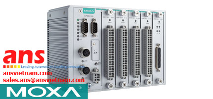
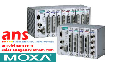
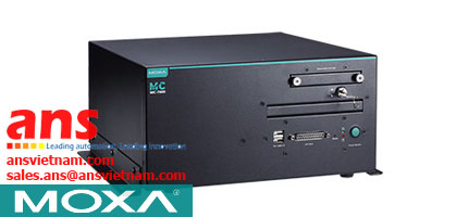
Overview
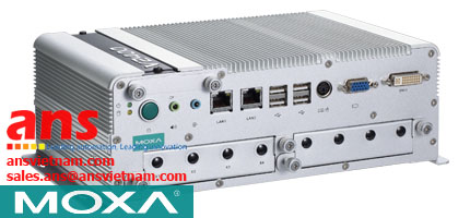
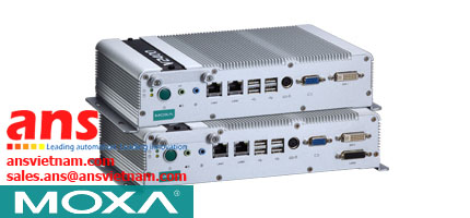
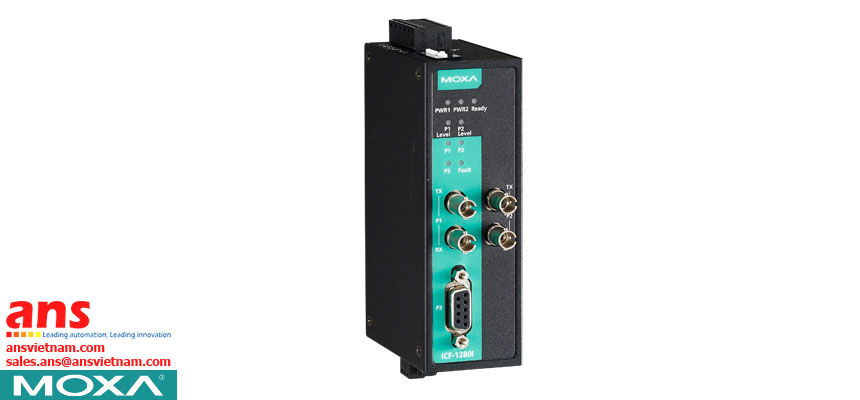
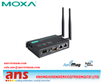
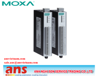
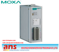
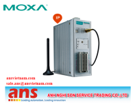
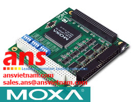
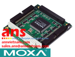
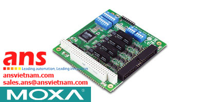
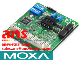
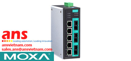
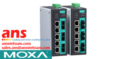
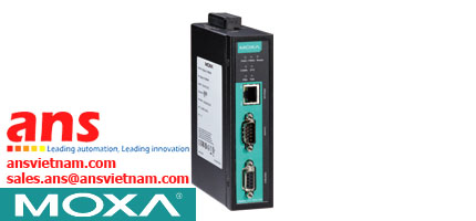
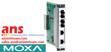
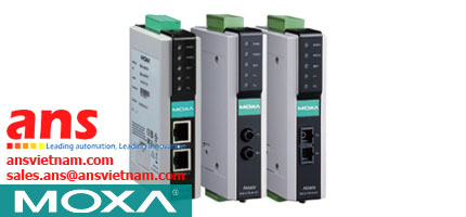
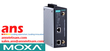
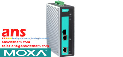
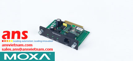
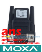
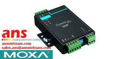
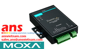
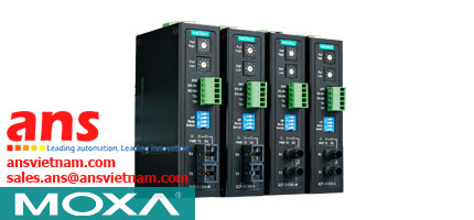
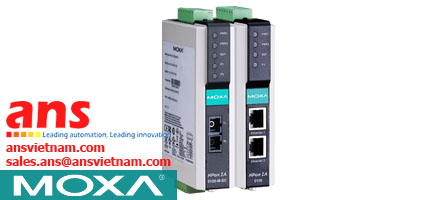
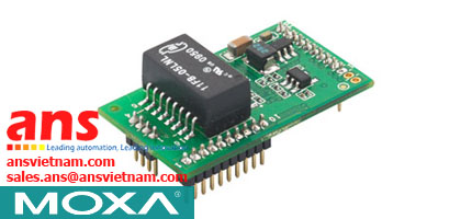
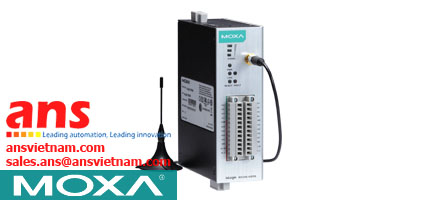
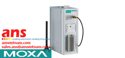
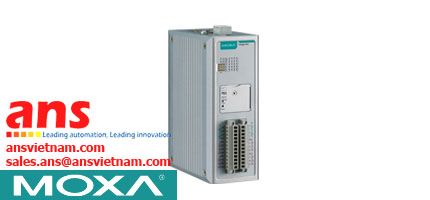
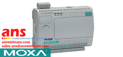
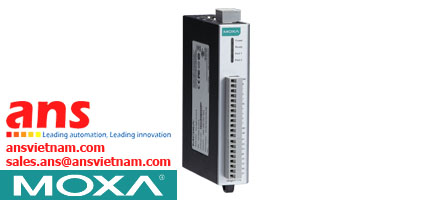
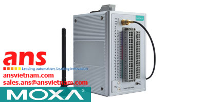
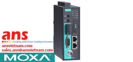
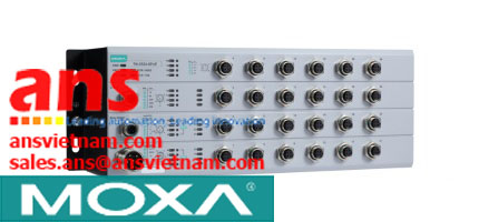
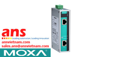
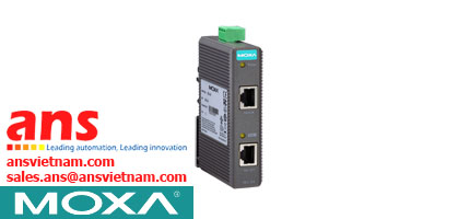
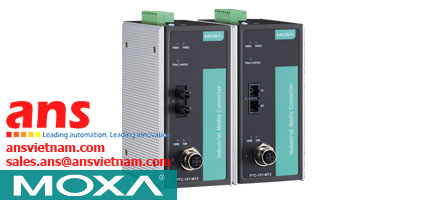
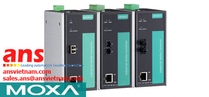
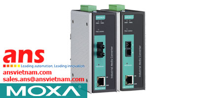
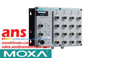
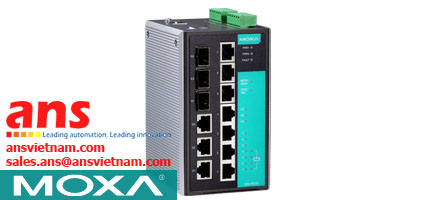
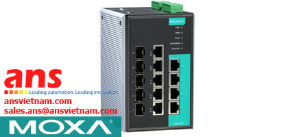
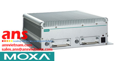
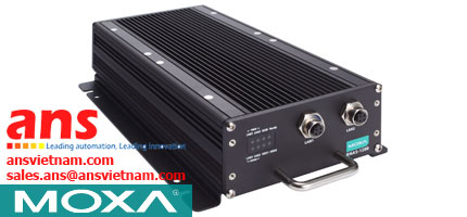
The ICF-1280I series industrial PROFIBUS-to-fiber converters are used to convert PROFIBUS signals from copper to optical fiber. The converters are used to extend serial transmission up to 4 km (multi-mode fiber) or up to 45 km (single-mode fiber). The ICF-1280I provides 2 kV isolation protection for the PROFIBUS system and dual power inputs to ensure that your PROFIBUS device will perform uninterrupted.
Remote Fiber Diagnosis
Optical fiber cables are often deployed for long distance communication and a fiber optic inspection pen is used by engineers to ensure proper communication quality of the fiber cable. The ICF-1280I series converters eliminate the need for a fiber optic inspection pen by providing a Remote Fiber Diagnosis function that uses DIP switch adjustments. There are two major functions provided by Remote Fiber Diagnosis: (1) determining which side (Tx or Rx) is causing the problem on the converter; (2) examining the fiber connections for the overall topology from any individual converter. Fiber cable abnormalities can be automatically detected and identified by the LED indicator even if it is not adjacent to the converter. Remote Fiber Diagnosis facilitates fiber cable deployment and management, and also significantly shortens troubleshooting time by examining fiber connections for the overall topology from any individual converter.
Redundant Ring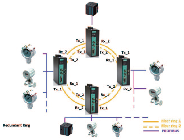
The ICF-1280I series converters can connect PROFIBUS devices in a redundant fiber ring topology. Use the DIP switch to configure all the ICF- 1280I converters to Redundant Ring mode. When a PROFIBUS master transmits a signal from one converter to the PROFIBUS slave devices, this signal will travel to all the converters around the ring until it returns to the original converter and terminate. The redundant ring structure ensures no packet loss with zero recovery time.
PROFIBUS Fail Safe
.jpg) Electrical noise may be generated when a PROFIBUS device malfunctions or the serial interface fails, resulting in bus failure. Traditional media converters transmit noise signals through the fiber wire to the other converter. This not only disrupts data communication between the two buses, but will also bring communication across the entire system to a halt. When this occurs, the engineers will not be able to easily locate the failed device because the entire PROFIBUS network is down. To avoid this situation, the ICF-1280I series converter has a mechanism to detect and recognize noise signals. If the bus fails on one side, the noise signal will not propagate through the ICF-1280I converter and affect additional bus segments. In addition, the ICF-1280I converter will also trigger an alarm to provide the location of the failure to the field engineer.
Electrical noise may be generated when a PROFIBUS device malfunctions or the serial interface fails, resulting in bus failure. Traditional media converters transmit noise signals through the fiber wire to the other converter. This not only disrupts data communication between the two buses, but will also bring communication across the entire system to a halt. When this occurs, the engineers will not be able to easily locate the failed device because the entire PROFIBUS network is down. To avoid this situation, the ICF-1280I series converter has a mechanism to detect and recognize noise signals. If the bus fails on one side, the noise signal will not propagate through the ICF-1280I converter and affect additional bus segments. In addition, the ICF-1280I converter will also trigger an alarm to provide the location of the failure to the field engineer.
Fiber Signal Intensity Diagnosis
In some circumstances, you may need to measure the receive level of the fiber optic port with a voltmeter, which can be connected while the device is operating (doing so will not affect data transmission). The measurement can be taken with a voltmeter and read on a PLC that uses floating high impedance analog inputs, which allows you to do the following: 1. Record the incoming optical power for later measurement (e.g., to indicate aging or damage). 2. Carry out a good/bad test (limit value).
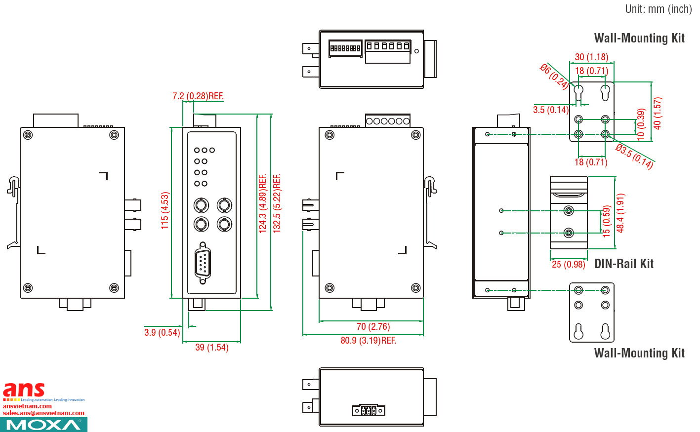
Dimensions
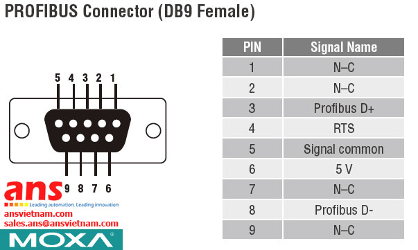
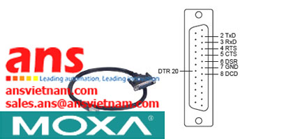
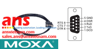
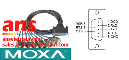
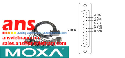
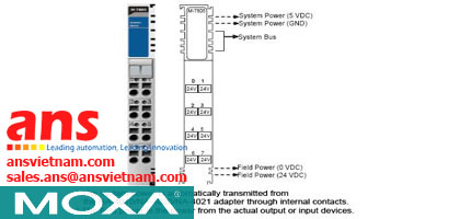
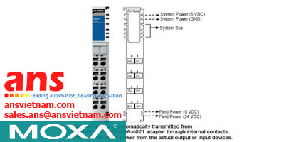
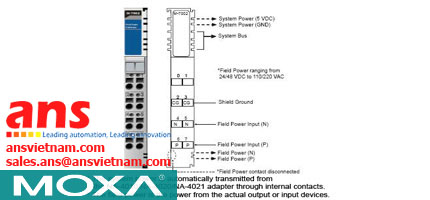
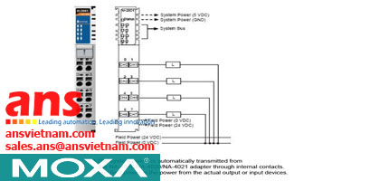
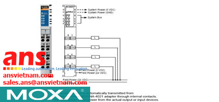
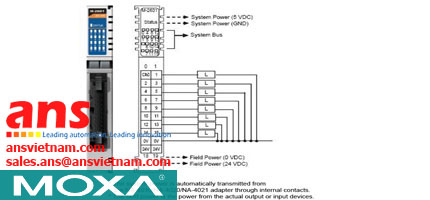
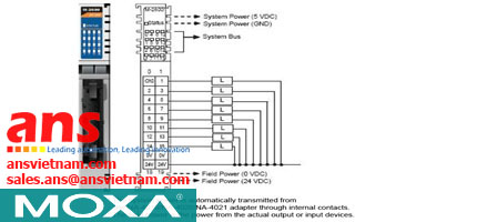
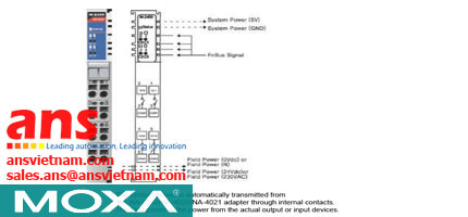
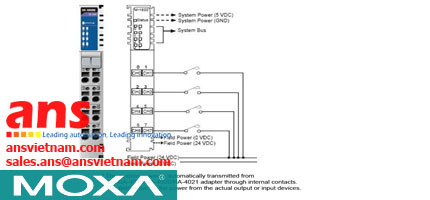
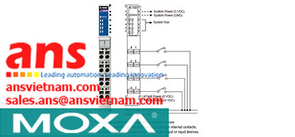
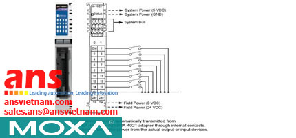
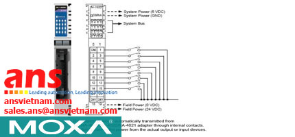
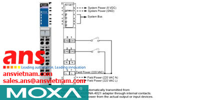
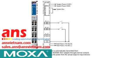
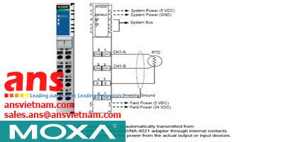
Pin Assignment
| • Technology | |
| Standards | IEC 61158-2 for PROFIBUS DP |
| • Interface | |
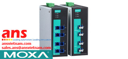
| P1/P2/P3 Ports | P1/P2 ports: ST optical fiber P3 port: PROFIBUS DP (DB9 female) |
| Relay Alarm | One relay output with current-carrying capacity of 2 A @ 30 VDC (Normal open) |
| LED Indicators | PWR1, PWR2, Ready, P1, P2, P3, Fault |
| DIP Switches | DIPs 1 to 4: Baudrate setting DIP 5: Fiber link monitor DIPs 6 to 7: Linear/Star mode (w/ optional P1/P2 disabled), Redundant Ring mode DIP 8: Remote Fiber Diagnosis |
| • PROFIBUS Communication | |
| Data Rate | 9.6, 19.2, 45.45, 93.75, 187.5, 500, 1500, 3000, 6000, and 12000 Kbps |
| Auto Baudrate | Yes |
| Isolation Protection | 2 kV |
| • Optical-Fiber Side | |
| Point-to-Point, Linear (Bus), Star, Redundant Topologies | |
| • Physical Characteristics | |
| Housing | Metal |
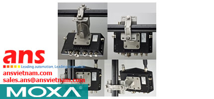
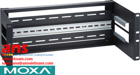
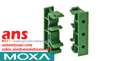
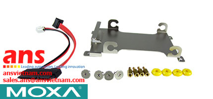
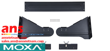
| Mounting | DIN rail, wall (with optional kit) |
| Dimensions | 39 x 115 x 70 mm (1.54 x 4.53 x 2.76 in) |
| Weight | 225 g (0.49 lb) |
| • Environmental Limits | |
| Operating Temperature | Standard Models: 0 to 60°C (32 to 140°F) Wide Temp. Models: -40 to 75°C (-40 to 167°F) |
| Storage Temperature | -40 to 75°C (-40 to 167°F) |
| Ambient Relative Humidity | 5 to 95% (non-condensing) |
| • Power Requirements | |
| Input Voltage | 12 to 48 VDC |
| Input Current | 315 mA @ 12 VDC |
| Connector | Terminal Block |
| Power Line Protection | Level 3 (2 kV) Surge Protection |
| Overcurrent Protection | 1.1 A |
| • Standards and Certifications | |
| Safety | UL 508 |
| Hazardous Location | UL/cUL Class I Division 2 Groups A/B/C/D, ATEX Zone 2 EEx nC IIC, IECEx |
| EMC | EN 55032/24 |
| EMI | CISPR 32, FCC Part 15B Class A |
| EMS | EN 61000-4-2 (ESD): Contact: 6 kV; Air: 8 kV EN 61000-4-3 (RS): 80 MHz to 1 GHz: 10 V/m EN 61000-4-4 (EFT): Power: 2 kV; Signal: 2 kV EN 61000-4-5 (Surge): Power: 2 kV; Signal: 2 kV EN 61000-4-6 (CS): 150 kHz to 80 MHz: 10 V/m EN 61000-4-8 (PFMF) |
| Green Product | RoHS, CRoHS, WEEE |
| Freefall | IEC 60068-2-32 |
| • MTBF (mean time between failures) | |
| Time | 1,567,875 hrs |
| Standard | Telcordia (Bellcore), GB |
| • Warranty | |
| Warranty Period | 5 years |
| Details | www.anhnghison.com |


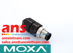


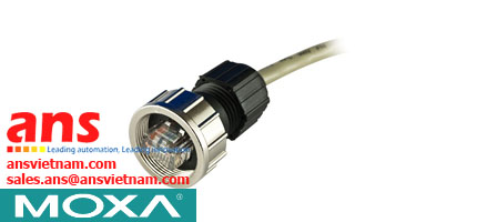


![Cables-CBL-M12[FF5P]-OPEN-100-IP67-Moxa-vietnam.jpg](/Images/products/thumb/Cables-CBL-M12[FF5P]-OPEN-100-IP67-Moxa-vietnam.jpg)